Introduction to Subtractive Synthesis
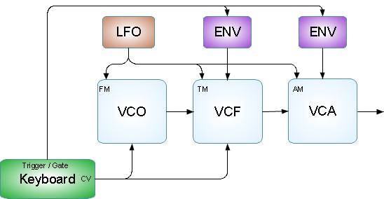
In Subtractive Synthesis, basic tones or waves are generated by an Oscillator (VCO) these tones are then fed into a filter (VCF) that removes, subtracts unwanted harmonics from the basic wave according an Envelope (ENV) signal. This resulting signal is than fed into an Amplfier (VCA) where the loudnes of the sound is determined by again a Envelope (ENV) signal. This basic combination can be varied in many ways e.g. different waves, different filters al kinds of (LFO) modulations etc.
In this introduction I wil try to explain how the basic princiles of analog subtractive
synthesis work. Waves generated by an oscillator
One of the basic building blocks of an subtracktive Synth is the oscillator also known as VCO
(Voltage Controlled Oscillator). This oscillator generates basic waves. A Wave is an repeating
cycle, its phase is expressed in degrees and runs from 0 to 360 degrees before starting over
again. The number of cycles or waves per second determine the ground Pitch or Frequency of
the wave and is expressed in Hz (Hertz). Wave forms offen used in Subtracktive Synths:
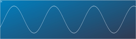
- Sinus
- Triangle

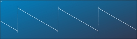
- Sawtooth
- Square or regulate square or Pulse
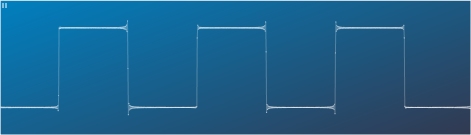 Pictures taken from HV-Formant analysis module in fast mode
The Sinus wave sounds very dry or clean, this is because it is an primary wave, it has only
base frequency. All the other waves e.g. Triangle, Saw and in fact any repeating wave form
you can think of, can be broken down in multiple Sinus waves. The sinus with the lowest
frequency in any wave determines the base frequency of the wave. All the other higher sinus
waves in the sound, we call Harmonics. The Triangle wave has only a few Harmonics, The
Sawtooth has many. The more Harmoics a waveform has the brighter it sounds we call this the
Timbre of the sound.
Next to frequency or pitch, a wave also has Amplitude (the hight of the wave form).
This determines how lowd the wave sounds. In an analog synt this amplitude is expressed in Volts.
The base frequency or pitch of the oscillator was in the analog era controlled by an Controll
Voltage (CV) comming from for instance a Key Board (1 volt / Octave) so as an example:
Key central A = 1 volt = 440 Hz one Octave up = 2 volt = 880Hz etc.. Next to this basic
frequency controll it is also possible to change the frequency a little bit by means of
an other controll signal comming from an other module called a "Low frequency Oscillator"
or LFO. This module can generate waves with low frequency or long cycle, for instance a
triangle with a cycle of two seconds (0.5 hz) If we now regulate this triangle to a small
Amplitude, low voltage and add this voltage to the (CV) controll voltage of the (VCO)
oscillator we get a slow drifting frequency. This kind of manipulation is called "Modulation"
and in this example (FM) Frequency Modulation. There are different kind's of Modulation
you can apply to an Oscillator. There is Frequency Modulation (FM), Amplitude Modulation
(AM), Ring Modulation (RM), Pulse Width Modulatio (PWM) etc.. These Modulation forms will
be explained later.
During the evolution of Subtractive Synths many forms of generating unique waves with all
kinds of harmonics where invented. With the digital viritual analog synth it is possible
to generate any kind of wave. The "HV-Formant" has an feature called Wave Splitting. With
this feature you can use 20% of an Sinus and 80% of an Triangle to generate a new wave.
The basic priciple however stayed the same. Now up to the Subtrackting part, removing
Harmonics from the waveform by means of an Filter.
Wave Harmonics subtrackted by an Filter
Although a synthesiser is much more than an instrument parrot, the development was highly
inspired on simulating the sound timbres and richnes of real instruments. Since the
Subtracktive Synt has as a limmited number of basic waveforms generate by the oscillator(s),
an extra device was needed to enhance the timbre of an basic sound. This is where the Voltage
Controlled Filter (VCF) comes in. With an filter you can remove (Subtrackt) Harmocis or
sinus waves of certain frequency's from the input signal. There are different types of
filtering, the most used are:
- Low Pass Filter (LPF)
With an LPF only the frequency's below a certain point are passed all the frequency's
above that point are rejected.
- High Pass Filter (HPF)
with an HPF only the frequency's above a certain point are passed and the lower
frequency's are rejected.
- Band Pass Filter (BPF)
With a BPF only the frequency's around a certain point are passed.
The frequency at the point where other frequency's are rejected is called the "Cutoff Frequency" (CUT)
Just as the basic frequency of the Oscillator (VCO), the Cutoff Frequency of the Filter (VCF) can be conrolled by means of an Controll Voltage (CV). If this Controll Voltage is comming from the keyboard than it is possible to let the Cutoff Frequency follow the pressed key (the Pitch) of the keyboard. This feature is called "Tracking". The ammount of Tracking is adjustable to suite your needs. Next to the tracking voltage, an voltage that discribes the timbre change of the sound over time is added. This is called the Timbre Envelope of the sound.
The Timbre Envelope is a curve that most offen follows an AR or ADSR sheme. The curve is started in most cases as a key is pressed on the keyboard. This strating of an envelope curve is called triggering or gating. If using a Lowpass filter (LPF) the envelope curve has the following effect on the filter:
A basic ADSR envelope (ENV)
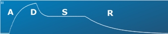
Picture taken from HV-Formant analysis module in slow mode
- Attack: The time it takes to reach full richness of the sound, or the time to reach the maximum cutoff frequency after the envelope is triggered.
- Decay: The dropback of timbre to a steady state.
- Sustain: The hight of the cutoff frequency at the steady state. Continues As long as the gate signal is pressent (the key is pressed).
- Release: The dampening of the sound if the tone dies. Occurs if the gate signal is removed (key is released).
An other voltage or controll signal that can be added to the Controll Voltage (CV) is an Voltage comming from an (LFO) Low frequency Oscillator. This is called Timbre Modulation.
Up to now we assumed an ideal filter, in real life however, nothing is ideal. The Cutoff Frequency of a filter is not absolute, it's not a strait line. The frequency's just above or below the Cutoff Frequency are not reduced to zero amplitude immediately but only reduced in amplitude. The amplitude reduction of frequency's above (LPF) or below (HPF) the Cutoff Frequency (CUT) is expessed in dB (DeciBell) per Octave and is called the filter slope. Most commonly used filter slopes are 12 and 24 dB/oct. The fact that these slopes are 12 and 24 db has to do with how they are electronicly build. The 24 dB/oct is much more complex and obviously sound's better.
On the other site of the Cutoff Frequency, the side where frequency's are passed through things are not ideal as well. On this side it is even possible that frequency's become lowder, higher in amplitued. We call this highly attracktive inperfectness the Resonance (RES) or Quality factor (Q) of the filter. This Resonace of the filter is on most filters adjustable. With an high Resonance or Quality factor it is even possible to let the filter generate frequency's. This is called self oscillation and is recognised by the feeeeew tone you don't expect.
Amplitude controlled by an Amplfier
A sound is not only characterised by its frequency and timbre, the loudness or Amplitude also changes over time. This change in loudness is achieved by means of an Voltage Controlled Amplfier (VCA). The controll voltage is generated by an envelope curve
most offen following an AR or ADSR curve and started by an gate or tigger comming from the keyboard. The effects are as lollows:
- Attack: The time it takes to reach the maximum amplitude of the sound after the envelope is triggerd, gate signal becomes pressent.
- Decay: The dropback in amplitude after the attack curve is completed.
- Sustain: The level at wich the sound is sustained after the Decay phase is completed. Continues as long as a key is pressed and the gate signal stay's pressent.
- Release: The time it takes for the sound to die out after the key is released, gate signal is removed.
An other signal that can be added to the Controll Voltage of the VCA is again a signal comming from an LFO. This is called Amplitude Modulation or AM.
An overview of terms used in Subtracktive Synthesis
What now follows is a list of already explained terms and some new additions that complete the principles of Subtracktive Synthesis. If you understand al the terms, you have some backgound knowledge to go and create sound's with these type of synthesisers, including the "HV-Formant".
- VCO
Voltage Controlled Oscillator. Used to generate basic waveforms. The base frequency of the wave is determined by the controll Voltage. Most synth's have at least 2 VCO's.
- VCF
Voltage Controlled Filter. Used to remove harmonic frequency's from the by the VCO's generated waveforms.
- VCA
Voltage Controlled Amplifier. Used to change the Amplitude of the waveform over time.
Mostly controlled by an ADSR Envelope.
- CV
CV means controll voltage. It is an combined signal that determines the frequency of the VCO, the cutoff frequency of the VCF or the amplification of the VCA.
- LFO
Low Frequency Oscilator, a module in the synth that generates waveforms with a long cycle or low frequency. The waveform signal is added to the CV to achieve modulation.
- Modulation
In principle modulation is changing the behaviour of one signal by means of an other signal. Basic modulation is achieved by adding the signal from an LFO to the CV of an module, but also signals from other sources can be used.
- FM
Frequency Modulation.
- TM
Timbre Modulation
- AM
Amplitude Modultation
- Envelope
Envelope signals are added to the CV of both the VCA and VCF to influence the behaviour of both modules over time. The Envelope signal is started (triggered) when a trigger or gate is received.
- ADSR
Attack, Decay, Sustain and release. These are the most used envelope curve segments. Each segment is adjustable in time. The Attack phase starts when the Envelope is triggerd (when a gate signal is received by the envelope). The Decay segment starts when the Attack phase is done. After the Decay phase is done the envelope signal stay's at an steady level, the Sustain level. This level is maintained as long as the gate signal is pressent. When the gate signal is removed the envelope immediately enters it's Release phase.
- GATE and or TRIGGER
These signals are used to start or restart the Envelope ADSR curve. The actual trigger signal is a short pulse used to start or restart the envelope. The gate signal is a longer signal that indicates that the envelope must continue e.g. An key on the keyboard is still pressed.
- PWM
Pulse Width Modulation is changing the Pulse width of the Square waveform of the VCO by means of an modulation signal. In the nomal situation the square, block or pulse wave has a duty cycle of 50%. This means the signal amplitude is high for 50% of the cycle and low for the other 50% of the cycle. With PWM you can change this percentage between 1 and 99% giving you an extra parameter to manipulate sounds.
- RM
Ring Modulation is another form of modulation often used in subtracktive synthesizers. The first electronics that performed RM actualy looked like a ring, this is where the name is comming from. In principle RM is nothing more than the multiplication of 2 signals, the effect however is much more complicate and interesting as expected. If two sinus waves with frequency f1 and f2 are multiplyed the resulting wave wil be a wave with 2 sinus waves, one with an frequency or pitch of (f1-f2) and the other with frequency of (f1+f2). Since we know that al repeating waves are build out a number of sinus waves one might expect a complicated wave if we multiply a trinagle wave with an saw wave.
- Syncing
Syncing is a feature found on most VCO's it is used to synchronise waves.
Synchronizing Waves is proberbly the most difficult feature on a Synth.
An wave is repeating it self after it's 360 degree cycle is complete, the time the cycle takes is called frequency and is expressed in Hertz (Hz). A tone or wave of 100Hz, repeats it self 100 time per second. Within each VCO a SYNC pulse is generate corresponding the basic frequency determined by CV. This pulse can be used to Sync waves on other VCO's e.g. to restart (begin at 0 degrees) an other wave, when this wave crosses 0 degrees. A Sync-Saw is one of the most populair synced waves.
Copyright Notice.
This article, including but not limited to all text and diagrams, is the intellectual property
of E.W. Fonken, and is Copyright © 2010. Reproduction or re-publication by any means whatsoever,
whether electronic, mechanical or electro- mechanical, is strictly prohibited under International Copyright laws.
The author grant the reader the right to use this information for personal use only,
and further allows that one (1) copy may be made for reference. Commercial use is prohibited
without express written authorisation from E.W. Fonken.
Page published and copyright © 16-4-2010 |